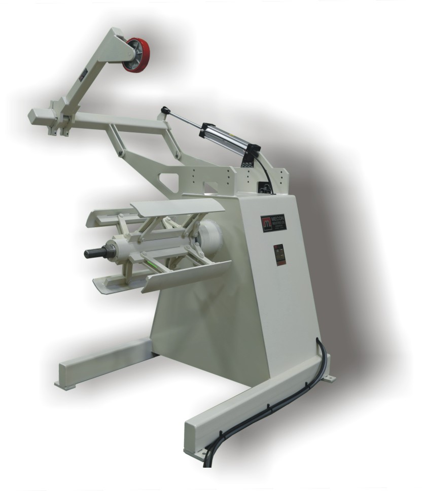
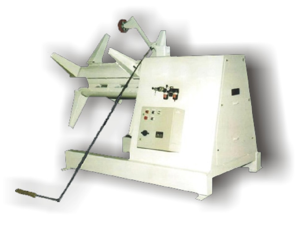
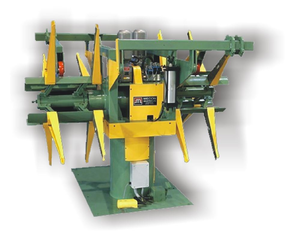
Reels: Single and Dual Spindle
The reel is used in most uncoiling, recoiling applications. It can be fitted with a variety of drive and braking systems, combined with coil cars. pinch rolls, power straighteners, overarms, rolling mills or configured as a stand alone machine.
Reels are the best choice for thin, prefinished and other mark sensitive materials.
They support the coil on the inside diameter and thus avoid stock deformation problems.
- Suited to wide ranges of material
- Give precise control of the material
- Can unwind or rewind
- Available as single or dual spindle
- Quick coil change times using dual spindle versions
- Available with various drive and brake systems
- Prevents damage to soft, prefinished, and mark sensitive material
Uncoiler Capacity by Series
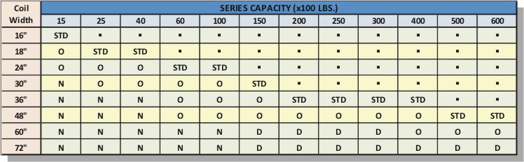
N = not available, O = optional, D=derate to next lower weight
Uncoiler Part Numbering
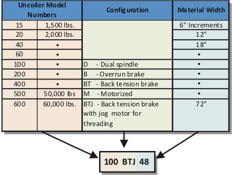
Example: 10,000lbs. uncoiler with Back Tension brake with Jog motor 48″ wide
Typical uncoiler description: model 100btj24.
- Single spindle uncoiler, with threading / rewinding drive, and air brake.
- Hydraulic system is enclosed within the uncoiler cabinet.
- 4 segment mandrel with ramp style hydraulic expansion.
- Expansion pressure is monitored and system automatically maintains clamping pressure.
- Threading / rewinding drive consists of a hydraulic motor, and an air release / spring actuated clutch, connected to the spindle by a chain drive.
- Air brake acts to provide braking to prevent coil overrun. A multipressure air circuit provides low braking during pay out and high braking when stopped. Air pressures are set with regulators mounted at the uncoiler cabinet.
- Electrical components are wired back to control panel. Operator controls are mounted in control panel.
Machine cabinet fully encloses the drive and hydraulic system; components are easily accessed by removing the panel on the back of the cabinet. - Moveable inner and outer keeper arms allow the coil to be positioned anywhere on the mandrel for alignment to the process.
- The uncoiler has an air brake to maintain coil tension during processing. A hydraulic motor, and clutch for jogging coil. Jog speed 4 rpm.
- The mandrel is 4 segments, with wedge style expansion and is hydraulically expanded/retracted. Id range 19″ to 24.5″, O.D. max. 60″ with coil car (optional 72″max O.D.)
OPTIONS:
- Coil Widths: 24″ Std., 30″-48″ Opt.
- Light to heavy duty braking systems
- Hydraulic or mechanical mandrel expansion
- Side shift
- Coil clamping arms with idle or driven wheels
- Combination with coil car, or coil elevator
- Quick release coil keepers
- Laser loop controls
- Laser centerline
UNCOILER OPTIONS Call (416)-751-1901
- COIL OVERARM
-IDLE WHEEL
-IDLE WHEEL with COIL GUARD
-HD AIR CYL, DUAL WHEEL
-FULL WIDTH IDLE ROLLER
-POWER WHEEL - OVERRUN BRAKE
- BACK TENSION AIR BRAKE
- AIR BRAKE,CLUTCH,JOG MTR
- DC MOTORIZED 3/4hp TO 20hp
- MAXIMUM COIL WIDTH
- HEAVY DUTY BTJ BASE
- TALL CABINET FOR UNDER LOOP
- PEDESTAL ELECTRICAL PANEL
- LINKAGE STYLE MANDREL
- WEDGE STYLE MANDREL
- HYD. MANDREL EXPANSION
- MAX COIL OD 60″
- MAX COIL OD 72″
- OUTBOARD SPINDLE SUPPORT
- QUICK RELEASE OUTER KEEPERS
- FULL DIAMETER BACK PLATE
- COIL REAR GUARDS
- COIL SIDE GUARD
- DANCER ARM LOOP CONTROL
- NON-CONTACT LASER LOOP CONTROL
- LASER CENTERLINE INDICATOR
- UNDER PADDLE LOOP CONTROL
- HYDRAULIC SIDE SHIFT BASE-18″
- TRAVELLING UNCOILER FOR ELEVATOR
- ROLLER COIL KEEPERS