Line 11-Uncoiler – Cradle – Servo Feeder-Straightener Press Feed LineMecon Industries Ltd2016-12-15T14:05:20-05:00
Line 11: Coil-Cradle-Straightener Servo Feeder

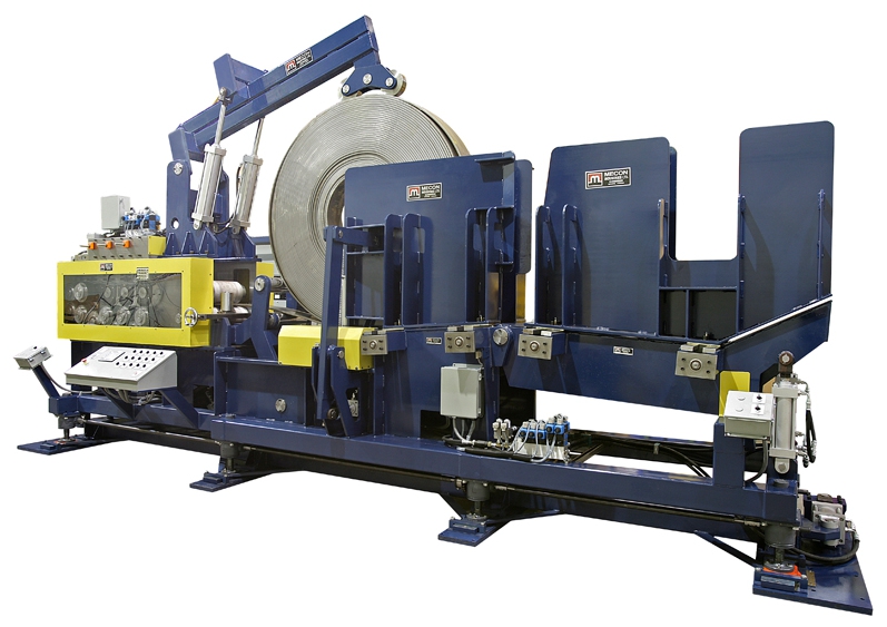
Model 200CSF18 Coil-cradle-straightener-feeder
- CAPACITY 20,000 LB.
- MAX. OD 72″
- MIN. ID 18″
- MAX. THICKNESS see chart
- PASSLINE HEIGHT 52″ TO 58″ POWER ADJUSTMENT
Coil-cradle-straightener-feeder: Model 200CSF18
- Coil Staging Ramp: The coil is set onto a fabricated Vee table with a pivot. Hydraulic cylinders lift the table upward to create a 5 degree down slope to the cradle rolls, or down for staging. A coil catcher / peeler catches and cushions the coil as it rolls into place on the cradle rolls. Coil catcher may be used to push the coil off the cradle rolls to the staging station.
- Side Guidance: Side walls on both sides of the coil are set to coil width to contain the coil and reduce telescoping. Side guide rolls are set in the walls beside the cradle rolls to reduce friction between the coil and the wall during feeding. Wall position is set by limit screws and open / closed by hydraulic cylinders. Walls open to rated coil width plus 10” to allow cutting and removing of coil retaining bands.
- vertical side guide rolls are set at the entry of the straightener
- Coil overarm: Telescoping overarm with dual rollers is set to hold the coil down onto the cradle and help contain the coil when the bands are cut. Actuated by hydraulic cylinders.
- Cradle: The coil is supported on 2 hardened cradle rolls X 7.750 inch dia..
- Cradle rolls are driven by a servo-gearmotor
- Cradle side plates are self centering and are power adjusted.
- Threading system: peeler / prebender pivots and extends to the side of the coil to guide and wrap the start of coil over the ramp rolls mounted between the cradle and the straightener. The entry pinch roll opens to catch the start of coil, closes to grip and drive the material through the straightener.
- Feeder-straightener: rolls are 1045 steel, 10.000″ diameter, induction hardenned to 56-58 Rc, and diameters are precision ground. Bearings are Heavy Duty rollers running on hardenned inner races with seals.
- 6 roll straightener: 3 upper rolls over 3 lower rolls.
- lower rolls are driven and fixed position
- upper rolls are not driven and are individually adjustable.
- Straightener rolls are adjusted by hydraulic motors, roll position is indicated by digital counters with .001″ resolution.
rolls are 1045 steel, 10.000″ diameter, induction hardened to 56-58 Rc, precision ground, shot peened and chrome coated for excellent wear resistance and grip
- 2 entry pinch rolls, upper and lower roll driven, grip the strip to drive material thru straightener without resetting.
- Rolls open up 3″ for easy threading.
- 2 exit feed rolls, upper and lower roll driven, grip the strip to drive material thru straightener without resetting.
- Lift system: The machine height is set by motorized worm screw jacks with 6″ adjustment. Jack feet are set onto floor pads. 2 guide posts mounted to the front mount plate prevent side movement.
- Controls: Control console contains the operator buttons and drive system including;
- Pendant jog control to allow operator to position strip from a remote location.
- Power on, Cradle sides in/out, Emergency Stop, Drives on/off, Roll controls, Cycle start/stop, Mode selection, Length and speed inputs, main power disconnect.
- Feed to length control requires a Press Operated Control Relay (Feed Cam) to close at start of feed, and remain closed until feeding is not permitted.
- Servo system: Bosch Indradrive, Yaskawa or equivalent, HMI to allow programming of system parameters, feed length, speed, and display of operating mode, fault status and code.
Back to Coil Handling….
Quote/info/contact….