Brake Press Set-up Aids
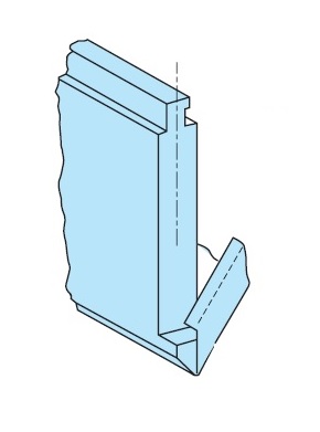
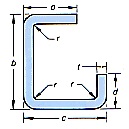
Box Forming
| Standard Guage for Steel Sheets | |||||||||||||||
|---|---|---|---|---|---|---|---|---|---|---|---|---|---|---|---|
| GAUGE | 3 | 4 | 5 | 6 | 7 | 8 | 9 | 10 | 12 | 14 | 16 | 18 | 20 | 22 | 24 |
| THICKNESS | 0.239" | 0.224" | 0.209" | 0.194" | 0.179" | 1.164" | 0.149" | 0.135" | 0.105" | 0.075" | 0.06" | 0.048" | 0.036" | 0.03" | 0.024" |
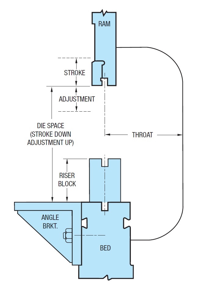
PressBrake Features
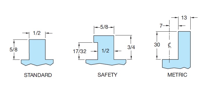
Common Types of Brake Punch Tongues – Others on Request
Brake Press Tonnage Chart
Tons Required Per Linear Foot to Bend Mild Steel Plate Having 60,000 PSI Tensile Strength
| Thickness of MATERIAL | Width of Die opening |
|||||||||||||||||||||||
|---|---|---|---|---|---|---|---|---|---|---|---|---|---|---|---|---|---|---|---|---|---|---|---|---|
| Gauge | Inches | 1/4" | 5/16" | 3/8" | 7/16" | 0.5 | 3/8” | 0.75 | 0.875 | 1 ” | 1.125 | 1.25 | 1.5 | 2" | 2.5 | 3" | 3.5 | 4" | 5" | 6" | 7" | 8" | 10" | 12" |
| 20 | 0.036 | 3.1 | 2.3 | 1.7 | 1.4 | 1.1 | ||||||||||||||||||
| 18 | 0.048 | 5.3 | 4 | 3 | 2.5 | 2.2 | 1.7 | 1.3 | ||||||||||||||||
| 16 | 0.06 | 9.6 | 7.1 | 5.6 | 4.5 | 3.8 | 2.8 | 2.2 | 1.8 | 1.5 | ||||||||||||||
| 14 | 0.075 | 11.9 | 9.2 | 7.6 | 6.3 | 4.7 | 3.5 | 3 | 2.5 | 2.1 | 1.8 | |||||||||||||
| 12 | 0.105 | 16.7 | 13.1 | 9.7 | 8 | 6.5 | 5.6 | 4.6 | 4.1 | 3.2 | ||||||||||||||
| 11 | 0.12 | 19.2 | 14.2 | 11.1 | 9 | 7.5 | 6.3 | 5.5 | 4.4 | 2.9 | ||||||||||||||
| 10 | 0.135 | 18.6 | 14.5 | 11.9 | 9.9 | 8.5 | 7.3 | 5.8 | 4 | |||||||||||||||
| 3/16" | 0.188 | 27.4 | 23.1 | 19.3 | 16.4 | 14.3 | 11.2 | 7.5 | 4.4 | |||||||||||||||
| 1/4" | 0.25 | 39.4 | 33.3 | 29.5 | 22.7 | 15.4 | 11.4 | 9 | 7.4 | 6.1 | ||||||||||||||
| 5/16" | 0.313 | 50.4 | 39.8 | 27 | 19.7 | 15.3 | 12.7 | 10.5 | 7.7 | |||||||||||||||
| 3/8" | 0.375 | 61.6 | 42.3 | 30.9 | 24 | 19.6 | 16.3 | 12.3 | 9.5 | |||||||||||||||
| 7/16" | 0.438 | 61.7 | 45.8 | 35.4 | 28.6 | 24.4 | 17.3 | 14.8 | 11.2 | |||||||||||||||
| 1/2" | 0.5 | 85.2 | 63.6 | 48.8 | 39.7 | 33.3 | 24.6 | 19.4 | 15.9 | 13.1 | ||||||||||||||
| 5/8" | 0.625 | 110 | 86.2 | 70 | 58.3 | 43.1 | 33.3 | 27.4 | 23.3 | 16.9 | ||||||||||||||
| 3/4" | 0.75 | 138 | 110 | 93 | 68.7 | 53.5 | 43.6 | 36.5 | 27.1 | 21 | ||||||||||||||
| 7/8" | 0.875 | 165 | 137 | 104 | 80.7 | 64.6 | 52.9 | 39.7 | 31.6 | |||||||||||||||
| 1" | 1 | 197 | 143 | 113 | 91.2 | 76.2 | 56.3 | 44.2 | ||||||||||||||||
| Notes: The tonnages indicated in bold italics are for die openings eight times the thickness of the metal. With an 8:1 die ratio, the inside radius of a right angle bend is approximately equal to the thickness of the material. |
||||||||||||||||||||||||
For other metals as compared to 60,000 PSI tensile strength mild steel adjust as follows:
- Soft brass: 50% of pressure listed.
- Soft aluminium: 50% of pressure listed.
- Stainless steel: 50% more than pressure listed.
- Chrome molybdenum: 100% more than pressure listed.
Brake Press Bending Allowance Chart
Bend Allowances for 90° Bends in Low‑Carbon Steel and Aluminum (Al)
| Bend Allowances for 90° Bends in Low-Carbon Steel and Aluminum | ||||||||||
|---|---|---|---|---|---|---|---|---|---|---|
| Bend allowance, inches, for bends with inside radius (r) of: | ||||||||||
| Metal thickness (t), in. | 1/32 in. | 1/16 in. | 3/32 in. | 1/8 in. | 1/4 in. | 1/2 in. | ||||
| Steel | Al | Steel | Al | Steel | Al | Steel | Al | (steel) | (steel) | |
| 0.032 | 0.059 | 0.057 | 0.066 | 0.068 | 0.079 | 0.082 | 0.093 | 0.095 | 0.146 | 0.254 |
| 0.05 | 0.087 | 0.078 | 0.101 | 0.091 | 0.114 | 0.105 | 0.129 | 0.118 | 0.168 | 0.276 |
| 0.062 | 0.105 | 0.095 | 0.118 | 0.108 | 0.132 | 0.12 | 0.145 | 0.133 | 0.183 | 0.29 |
| 0.078 | 0.128 | 0.116 | 0.142 | 0.131 | 0.155 | 0.144 | 0.169 | 0.157 | 0.202 | 0.31 |
| 0.09 | 0.146 | 0.13 | 0.16 | 0.144 | 0.173 | 0.157 | 0.187 | 0.17 | 0.217 | 0.324 |
| 0.125 | 0.198 | 0.175 | 0.211 | 0.189 | 0.224 | 0.203 | 0.243 | 0.216 | 0.26 | 0.367 |
| 0.188 | 0.289 | 0.302 | 0.217 | 0.316 | 0.283 | 0.329 | 0.297 | 0.383 | 0.443 | |
| 0.25 | 0.382 | 0.395 | 0.409 | 0.365 | 0.424 | 0.378 | 0.476 | 0.519 | ||
| 0.313 | 0.488 | 0.501 | 0.515 | 0.569 | 0.676 | |||||
| 0.375 | 0.593 | 0.607 | 0.661 | 0.768 | ||||||
| 0.437 | 0.699 | 0.752 | 0.86 | |||||||
| 0.5 | 0.845 | 0.952 | ||||||||
| Bend Allowances for 90° Bends in Low-Carbon Steel and Aluminum (Metric) | ||||||||||
|---|---|---|---|---|---|---|---|---|---|---|
| Bend Allowance (mm) for Bends with Inside Radius (r) of: | ||||||||||
| Metal Thickness ( t ), mm (Inches) | 0.8 mm(1/32") | 1.6 mm(1/16") | 2.4 mm(3/32") | 3.2 mm(1/8") | 6.4 mm(1/4") | 12.7 mm(1/2") | ||||
| Steel | Al | Steel | Al | Steel | Al | Steel | Al | Steel | Steel | |
| 0.8 (0.032") | 1.5 | 1.4 | 1.7 | 1.7 | 2 | 2.1 | 2.4 | 2.4 | 3.7 | 6.5 |
| 1.3 (0.050") | 2.2 | 2 | 2.6 | 2.3 | 2.9 | 2.7 | 3.3 | 3 | 4.3 | 7 |
| 1.6 (0.062") | 2.7 | 2.4 | 3 | 2.7 | 3.4 | 3 | 3.7 | 3.4 | 4.7 | 7.4 |
| 2.0 (0.078") | 3.3 | 2.9 | 3.6 | 3.3 | 3.9 | 3.7 | 4.3 | 4 | 5.1 | 7.9 |
| 2.3 (0.090") | 3.7 | 3.3 | 4.1 | 3.7 | 4.4 | 4 | 4.8 | 4.3 | 5.5 | 8.2 |
| 3.2 (0.125") | 5 | 4.4 | 5.4 | 4.8 | 5.7 | 5.2 | 6.2 | 5.5 | 6.6 | 9.3 |
| 4.8 (0.188") | 7.3 | 6.5 | 7.7 | 5.5 | 8 | 7.2 | 8.4 | 7.5 | 9.7 | 11.3 |
| 6.4 (0.250") | 9.7 | 8.6 | 10 | 8.9 | 10.4 | 9.3 | 10.8 | 9.6 | 12.1 | 13.2 |
| 8.0 (0.313") | 12 | – | 12.4 | – | 12.7 | – | 13.1 | – | 14.5 | 17.2 |
| 9.5 (0.375") | 14.4 | – | 14.7 | – | 15.1 | – | 15.4 | – | 16.8 | 19.5 |
| 11.1 (0.437") | 16.7 | – | 17.1 | – | 17.4 | – | 17.8 | – | 19.1 | 21.8 |
| 12.7 (0.500") | 19.1 | – | 19.4 | – | 19.7 | – | 20.1 | – | 21.5 | 24.2 |
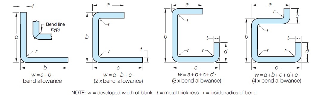
w = a + b + c + d + e –
(4 x bend allowance)
w = a + b –
(single bend allowance)
w = a + b + c –
(2 x bend allowance)
w = a + b + c + d –
(3 x bend allowance)
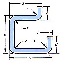
Note: w = developed width of blank, t = metal thickness, r = inside radius of bend
Notes of Interest
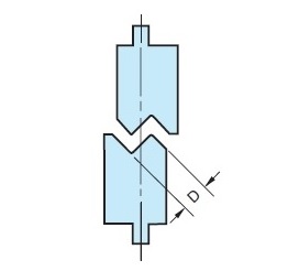
Offset Dies
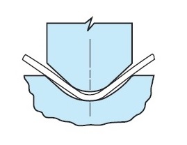
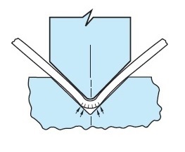
Tonnage requirements can be reduced by air bending rather than bottoming (compromising on accuracy), and also by using larger radii on the forming points.
Radius Dies
Fracturing
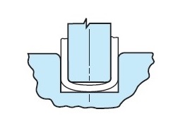
Channel Dies
Press Brake Deflection
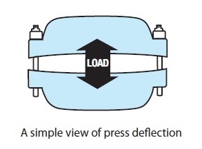
In some presses the bed and ram do not deflect in an even curve. The deflection can be mapped out for a press that is doing a particular job by taking accurate measurements along the length of test pieces. This deflection curve can then be reproduced by the machine.
- Shim the bottom (crowning) die manually by using a roll of adding machine paper. Start in the middle with a short piece, gradually increasing the length of the layers. The number of layers may be increased or decreased as required. Three layers of paper equals approximately 0.012-0.015 inches.
- If you are working within a small range of material thickness, the crown required may be reasonably consistent. Map out the deflection and machine it into the riser block.
- If you have dedicated tooling for a specific job, map out the deflection and have the tooling crowned.
- Purchase a “Mecon Deflection-Compensating Die Holder.”
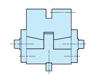
Mecon Deflection-Compensating Die Holder.
- Multi point calibrating adjustment.
- Crown read-out indicators.
- Patent#1234039
Thinking Safety
Our dies are never intended to be used in equipment without a means provided to prevent hands or other body parts from entering or remaining in the die space at any time.
- Require that dies be set only by a qualified, safety-conscious die-setter.
- Insist that the die-setter be fully familiar with the press or machine’s manual.
- Provide all point-of-operation guards or devices necessary to avoid exposing any part of the operator’s body to the closing of the machine or press.
- Provide hand tools to insert, hold, and remove material, and to keep hands at a safe distance from the point of operation.
- Insist on safety practices and procedures and enforce them daily.
- Follow the instructions provided in the manual for the machine in which dies are being installed and operated.
- Ascertain that operators are trained in safety procedures, and arrange for periodic inspections to ensure that those procedures are being followed.
- Make available such safety-standard approved devices as pull-backs, fences, and infrared light curtain and controls for all press equipment. Two-button operation may also be necessary in some instances.