The Material
The internal stresses often vary from the outer wraps to the inner wraps and from the center to the edges. The strip is unwound, slit to width and rewound. Center slit material often yields the best material, edge cuts often yield the worst. When the internal stresses are not balanced, the slit material will have camber. The greater the stress imbalance, the worse the camber. In some instances, additional processing will be necessary to balance the internal stresses and eliminate camber. Poor material is a leading cause of difficulty in tracking the strip through the entire system. Camber problems will consume your profits!
To avoid many coil-handling problems, insist on quality material, reject that which does not meet your standards, and use the proper uncoiling system.
Productivity
Selecting the proper options for your system will provide big paybacks in productivity gains.
- Eliminate waiting time for overhead cranes or lift trucks by installing coil cars and coil storage ramps Coils can be staged when convenient and are ready when the system needs them
- Reduce handling time and increase safety with coil clamping arms and threading equipment
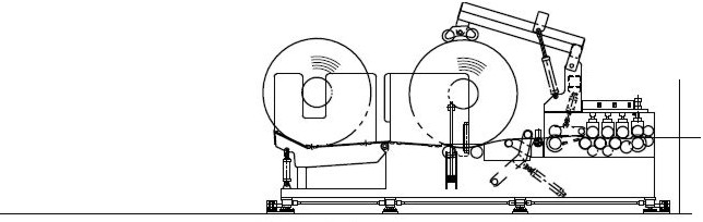
- Use dual spindle uncoilers when feeding high demand systems like rolling mills or systems using partial coils
- Use sonar loop controls to smooth the uncoiling – straightening process, maintain proper loop geometry, and deliver more consistent material to the feeder
- Use a side shift base on the uncoiler to allow easy coil alignment and adapting for camber during processing
- Purchase the best material possible to ensure good quality, consistent parts
SUGGESTED SYSTEM ARRANGEMENTS
Mecon Industries Limited manufactures a variety of coil processing systems.
Many factors should be considered when determining the optimum arrangement.
• Crane capacity
• Lift truck capacity
• Mark sensitivity
• Material width
• Material strength
• Coil handling: – load and unload partial coils, or run full coils to end
• Coil inside diameter
• Coil outside diameter
• Production required: -feed length, speed, feed angle, feed time
• Budget
Coil Lines
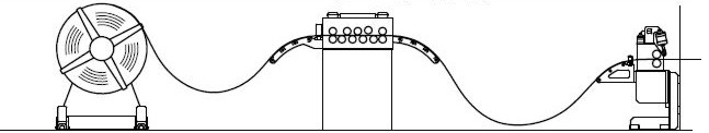
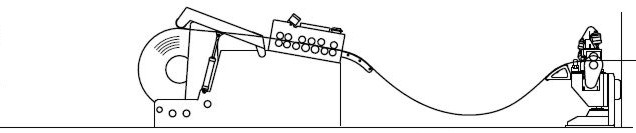
LINE 1
- BACK TENSION UNCOILER
- POWERED STRAIGHTENER
- PRESS-MOUNTED SERVO ROLL FEED
LINE 2
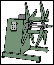
- MOTORIZED UNCOILER
- POWERED STRAIGHTENER
- SERVO ROLL FEEDER
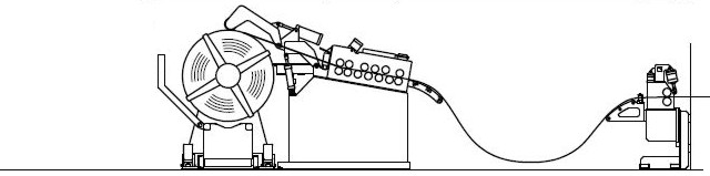
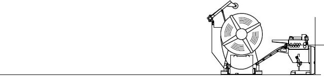
LINE 3
- POWERED TRAVEL & LIFT COIL CAR
- BACK TENSION UNCOILER (WITH JOG MOTOR)
- THREADING STAND
- POWERED STRAIGHTENER
- SERVO ROLL FEEDER
LINE 4
- MOTORIZED UNCOILER
- HOLD-DOWN ARM
- SERVO FEEDER-STRAIGHTENER
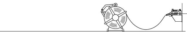
LINE 5
- MOTORIZED UNCOILER
- UNDER PADDLE LOOP CONTROL
- SERVO FEEDER-STRAIGHTENER
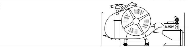
LINE 6
- POWERED TRAVEL & LIFT COIL CAR WITH IDLE ROLLS
- MOTORIZED UNCOILER WITH SONAR LOOP CONTROL
- OVERARM WITH COIL GUARD
- SERVO FEEDER-STRAIGHTENER (WITH THREADING OPTION)
LINE 7
- POWERED TRAVEL & LIFT COIL CAR WITH IDLE ROLLS
- BACK TENSION UNCOILER (WITH JOG MOTOR & SIDE SHIFT)
- PULL-OFF PINCH STAND WITH OVER-ARM
- COIL GUARD
- FEEDER-STRAIGHTENER
(WITH THREADING OPTION)
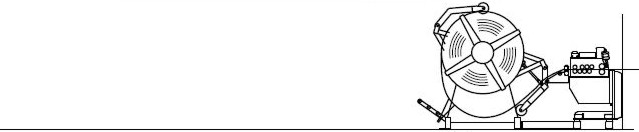
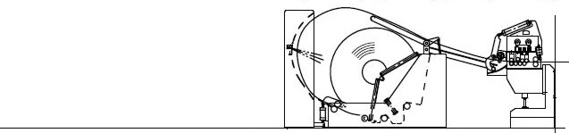
LINE 8
- COIL CRADLE
- COIL THREADING AND PREBENDER
- SERVO FEEDER STRAIGHTENER
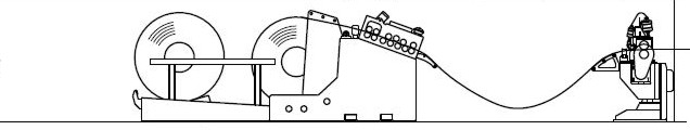
LINE 9
- COIL STORAGE RAMP
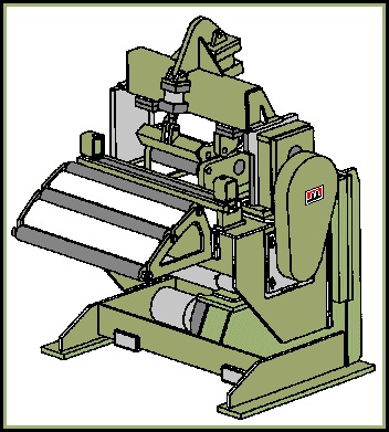
- COIL CRADLE STRAIGHTENER
- SERVO ROLL FEEDER
LINE 10
- COIL CRADLE STRAIGHTENER (WITH THREADING OPTION)
- FLOOR-MOUNTED SERVO ROLL FEED
LINE 11
- SERVODRIVEN COIL-CRADLE-STRAIGHTENER-FEEDER
- HEAVY DUTY DEKINKER AND COIL THREADER
- WITH COIL STAGING RAMP
- SIDE SHIFT BASE
ACCUMULATION LOOPS and PITS

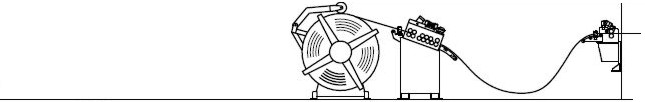
Most systems require an accumulation loop. The accumulation loop is used to allow the uncoiling process to payout at a nearly continuous rate while the feeding equipment stops and starts. Ideally the loop will accumulate at least 2 feed lengths of material. Thickness, material yield strength, and feed length are important factors to consider when determining loop geometry. The loop must store sufficient material to allow smooth operation. The material must not be curved smaller than the minimum bend radius to ensure that the proper loop shape is maintained and kinking does not occur:
• The loop length should be 1000 to 1400 times the material thickness.
• Ramp rolls should support the material as it enters and exits the loop.
A pit is recommended if the required LOOP HEIGHT, is greater than the process height
| Loop Height (H) | MAXIMUM FEED LENGTH (inches) | ||||||
|---|---|---|---|---|---|---|---|
| 135" | 130 | 117 | 106 | 96 | 88 | 81 | 75 |
| 120" | 111 | 99 | 89 | 80 | 73 | 66 | 61 |
| 105" | 92 | 81 | 72 | 64 | 58 | 53 | 48 |
| 90" | 74 | 64 | 56 | 50 | 44 | 40 | 36 |
| 75" | 57 | 48 | 41 | 36 | 32 | 29 | 26 |
| 60" | 40 | 33 | 28 | 24 | 21 | 19 | 17 |
| 45" | 25 | 20 | 17 | 14 | 12 | 11 | 10 |
| 30" | 12 | 9 | 8 | 6 | 6 | 5 | 4 |
| 90" | 120" | 150" | 180" | 210" | 240" | 270" | |
| LENGTH OF LOOP | |||||||
| Maximum Feed Length | Accumulation | MINIMUM LOOP HEIGHT (inches) | ||||||
|---|---|---|---|---|---|---|---|---|
| 80" | 120" | 95 | 104 | 112 | 120 | 127 | 134 | 141 |
| 70" | 105" | 86 | 95 | 103 | 110 | 117 | 124 | 130 |
| 60" | 90" | 78 | 86 | 94 | 101 | 107 | 113 | 119 |
| 50" | 75" | 69 | 77 | 84 | 90 | 96 | 102 | 107 |
| 40" | 60" | 60 | 67 | 73 | 79 | 85 | 90 | 95 |
| 30" | 45" | 50 | 57 | 62 | 68 | 72 | 77 | 81 |
| 20" | 30" | 40 | 45 | 50 | 54 | 58 | 62 | 65 |
| 10" | 15" | 27 | 31 | 34 | 38 | 40 | 43 | 46 |
| 90" | 120" | 150" | 180" | 210" | 240" | 270" | ||
| LENGTH OF LOOP ( L ) | ||||||||
| STEEL COIL WEIGHT CAULATOR coil weight LBS / INCH | ||||
|---|---|---|---|---|
OUTSIDE DIAMETER OF Coil | 72" | 1099 | 1067 | 1028 |
| 66" | 915 | 882 | 843 | |
| 60" | 746 | 714 | 675 | |
| 54" | 593 | 561 | 522 | |
| 48" | 457 | 425 | 385 | |
| 42" | 336 | 304 | 265 | |
| 36" | 232 | 200 | 161 | |
| 30" | 144 | 112 | 72 | |
| 24" | 71 | 39 | 0 | |
| _______________ | 16" | 20" | 24" | |
| INSIDE DIAMETER OF COIL | ||||
MATERIAL WEIGHT FACTORS
- Aluminum x .35
- Brass x 1.08
- Copper x 1.14
- Stainless x 1.00
multiply CHART VALUE by COIL WIDTH
eg: 60″ OD and 20″ ID, 10″ wide coil
=714 lbs/in x 10″ wide coil = 7,140 lbs
| Standard Guage for Steel Sheets | |||||||||||||||
|---|---|---|---|---|---|---|---|---|---|---|---|---|---|---|---|
| GAUGE | 3 | 4 | 5 | 6 | 7 | 8 | 9 | 10 | 12 | 14 | 16 | 18 | 20 | 22 | 24 |
| THICKNESS | 0.239" | 0.224" | 0.209" | 0.194" | 0.179" | 1.164" | 0.149" | 0.135" | 0.105" | 0.075" | 0.06" | 0.048" | 0.036" | 0.03" | 0.024" |
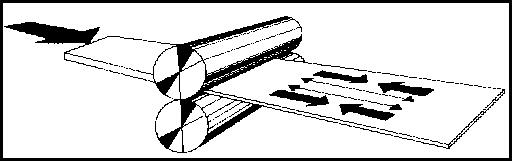
The Uncoiling Problem
The strip is slit to width. When internal stresses are not balanced, the slit material will have camber. The greater the stress imbalance, the worse the camber. Camber is a leading cause of difficulty in tracking the strip through the entire system. To avoid many of the problems of coil handling, insist on quality material, reject that which does not meet your standards, and use the proper uncoiling system.The Two Basic Systems
Electronic Roll Feeding
Ease of set up is a key feature. ERF’s take less time to set up than mechanical feeds and trial and error adjustment: at the control panel, just enter feed length, speed, and press “start.” Mecon will size the drive and set the acceleration and deceleration to best match the production requirements.
When possible, lower accelerations and speeds are used. This gives increased accuracy, smoother material flow, and eases the load on the uncoiling system. Another outstanding advantage of the ERF units is their ability to easily adapt to the press feed angle.
.