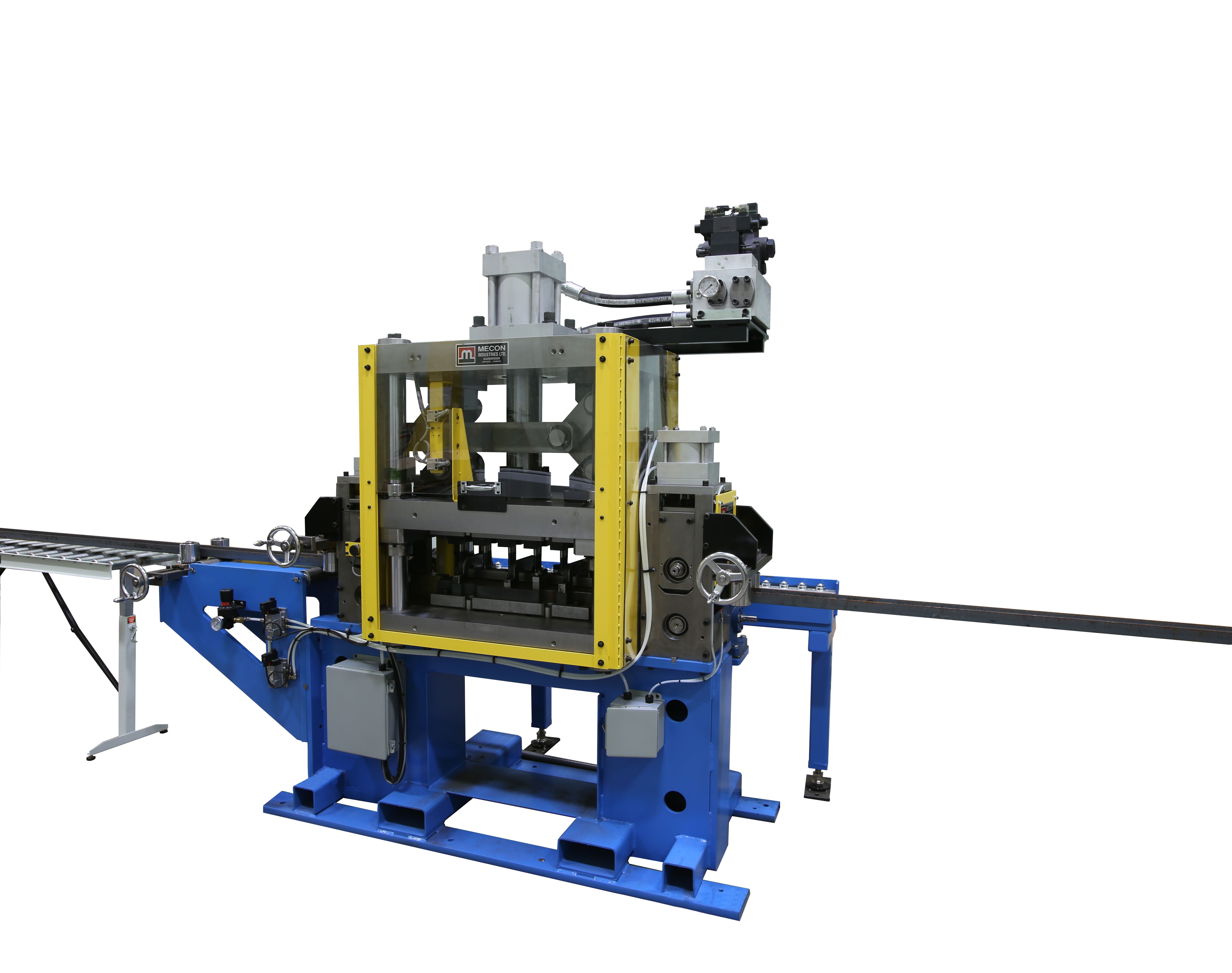
Custom, Purpose built systems. C-Channel punching Machine
[embedyt] https://www.youtube.com/watch?v=BIA7KHf4xeE[/embedyt]C-Channel Processing line, Customizable to any requirement
Requirement:
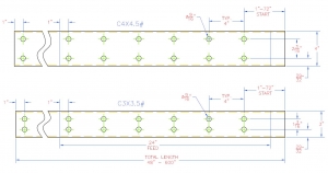
Machine to punch holes in 2” and 3” C-channel Various lengths from 30 to 50 ft.
-C3 X 3.5 2 rows of holes 9/16” dia., 1- 3/16” side to side, 4” pitch
-C4 X 4.5 2 rows of holes 9/16” dia., 2- 3/16” side to side, 4” pitch
Process requirement:
-Target Performance: Process 3000+ft of channel per hour.
-Operator to manually load pre-cut to length material and feed into machine.
-Machine closes entry pinch rolls, aligns the starting edge and proceeds to process the channel, punching 12 holes per press stroke until channel finished.
Proposed Solution:
The system to consist of the following components:
Entry conveyor:
-Non-powered, 40ft long, 3” diameter rolls on 18” centers.
-Passline height 42” (Width TBD, quote based on 16” wide conveyor)
-2 pairs of self-centering side guides to align the channel to the punching system
System Frame: the entry pinch rolls, the Hydraulic press components, exit pinch rolls.
Material entry laser sensor:
-Precision laser system to detect start of channel. Once detected, entry pinch rolls close and the system is ready to start.
Entry Pinch Rolls:
-Bottom roll – Servo driven 6” diameter feed roll, drives the bottom surface of the channel,
-Top roll –6” diameter x 1.5” wide contacts inner surface of web.
-Top roll pinch force applied by air cylinder, pressure set manually.
-Rolls are 1045 steel, induction hardened to 55-60 Rc, precision ground, surface treated and chrome coated for a hard, high friction surface giving excellent grip and long life.
Hydraulic punch press with tooling mount for offset beam processing
-9/16″ punch tool 1 for 3.5” channel 12 punches
-9/16″ punch tool 2 for 4.5” channel 12 punches
Hydraulic punch press 50 tons (to be confirmed)
-Press bed has 12 punch and die retainers for 9/16” holes mounted in 2 rows of 6, one set for 1 3/16”, one set for 2- 3/16”
-Punch heights are staggered in ¼” steps to punch 4 holes at the same time.
-First to contact punches positions 1, 2, 11, 12 (full length)
-2nd to contact positions 3, 4,9,10 (1/4” shorter)
-3rd to contact positions 5,6,7,8 (1/2” shorter)
-Opening for maintenance: 4”
-Opening when in Automatic: 1”
-Tools mounted in sliding holder, adjustable +/- 1” from center (confirm)
-Minimum 1-1/4” from outer edge of channel.
-Opening for maintenance: 4”
-Opening when in Automatic: 1” set by limit switch
-Fixed height stripper bar.
Exit Pinch Rolls: Same construction as entry pinch rolls
Exit Material Sensor:
-Signals exit pinch rolls to close when material is thru pinch rolls and open when the processed material leaves the system.
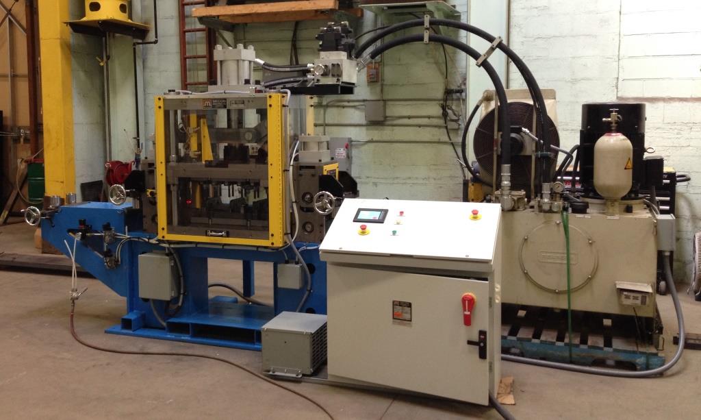
Control System:
-Part pattern to be stored in control system memory.
-Control console contains the HMI (touch screen for machine control), main power disconnect, and Emergency Stop.
-Safety circuits: Dual Channel E-stop, Dual channel Gate monitor
Estimated performance:
24” progression .75
Punch cycle time 1.25sec
Average process speed target 50ft/min
Uncoilers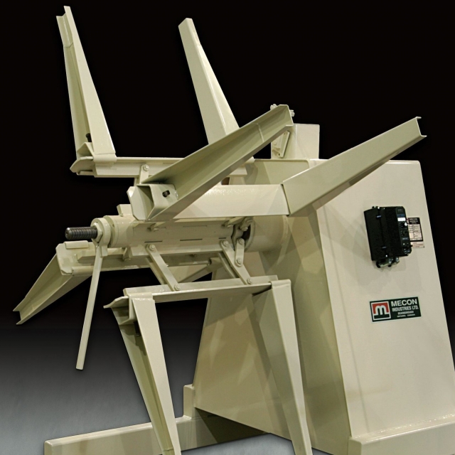
Straighteners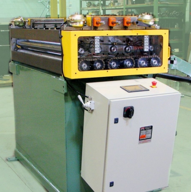
Servo Feeders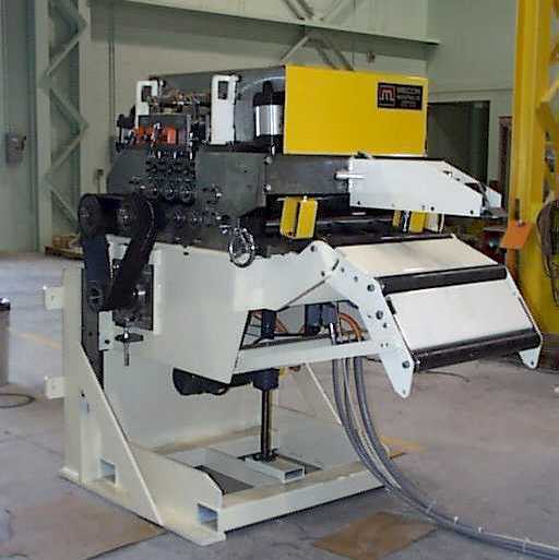
Feeder Straighteners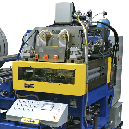
Coil Lines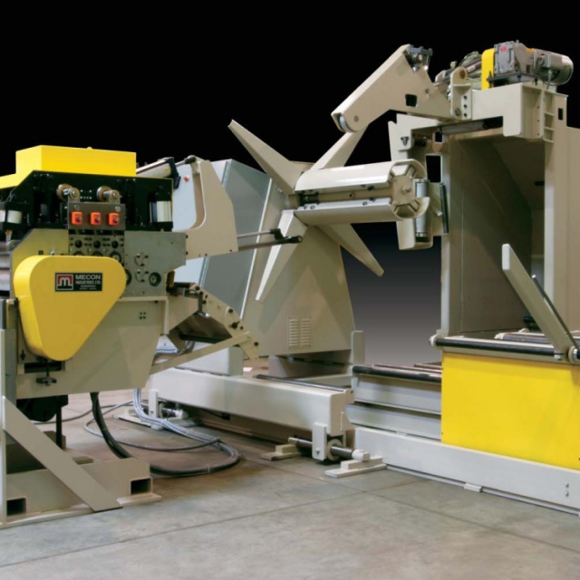
Options