Typical system requirements and proposed solutions:
#15918 20Klb x 36 .354″ HSLA#15409 20Klb x 48 CTL
#11233 20Klb x 18 HSLA
#3120 50Klb x 72 Conventional
#16675 C-Channel Punching System
System #15918
Requirement:
Coil feed system for Minster Press
- 20,000 lb x 36” wide capability
- Material thicknesses: .236″ .354″
- Material:Steel
- Yield Strength 550 Mpa (80,000 psi) to 650 Mpa (95,700 psi)
- Feed length: 12″ @30 spm, 24″ max
- Hands free threading, operator only cuts banding.
- Max coil width: 36″
- Servo powered straightener-feeder
- Servo pilot release
- Feed roll accuracy of +/-0.002”
- Roll coil keepers
- Compact line design
- Quick/easy coil changeover
Important Considerations:
Tight tolerance on length.
Flatness
Coil Handling streamline and automate
PROPOSED SOLUTION
Coil car – 200cc with Coil keeper arms and Powered Rollers
- A coil car with powered lift of 20″ and power travel.
- Travel on tracks to transfer the coil from the park position to the uncoiler, or from the uncoiler back for storage.
- Coil rests on powered rollers. The rolls are used to aid in threading thicker materials into the straightener.
- Traverse, and lift functions are controlled manually from a central control station.
Uncoiler – 200btj36
- Uncoiler has an air brake to maintain coil tension during processing.
- Hydraulic motor, and clutch for jogging coil. Jog speed 4 rpm.
- Air brake pressure is set at the operator screen as 1 to 100 % by an analog voltage controlled air regulator.
- Heavy duty back tension brake and jog drive to meet the demands of thicker and higher strength materials.
- Mandrel is 4 segments, with wedge style expansion and is hydraulically expanded/retracted.
- Inside diameter range of 19 to 24.5″
Coil over arm with power wheel.
- Over arm clamps onto the coil to restrict the coil end when the straps are cut.
- Power wheel is driven by hydraulic clutch-motor and helps drive the material into the loop during threading.
- Grove cut into centerline of the wheel ¼”dp x 1.5”wide for straping.
Power Pull Off Rolls. 8pr36-10 hp
- Power pinch rolls pull the steel off the coil and feed the accumulation loop.
- Upper roll is driven by an AC brake-motor with integral worm gearbox.
- Motor speed is controlled by a variable frequency drive..
- Power roll pivots down to clear the loop during threading.
- When the strip is between the rolls and ready to be clamped, the lower roll pivots up to pinch the strip against the upper roll.
- Rolls are 8″ dia. X 18″ face width, made from 1045 steel, induction hardened to 55-58 Rc., finish ground, and shot peened and chromed.
- Screw adjust side guide rolls are mounted on the exit side of the pull off rolls. These rolls provide material guidance during rewinding of partial coils.
Pull Roll Frame and Material guides. .
- A floor base carries the pinch rolls, the pinch roll loop control and support rollers, and provides a vertical guard.
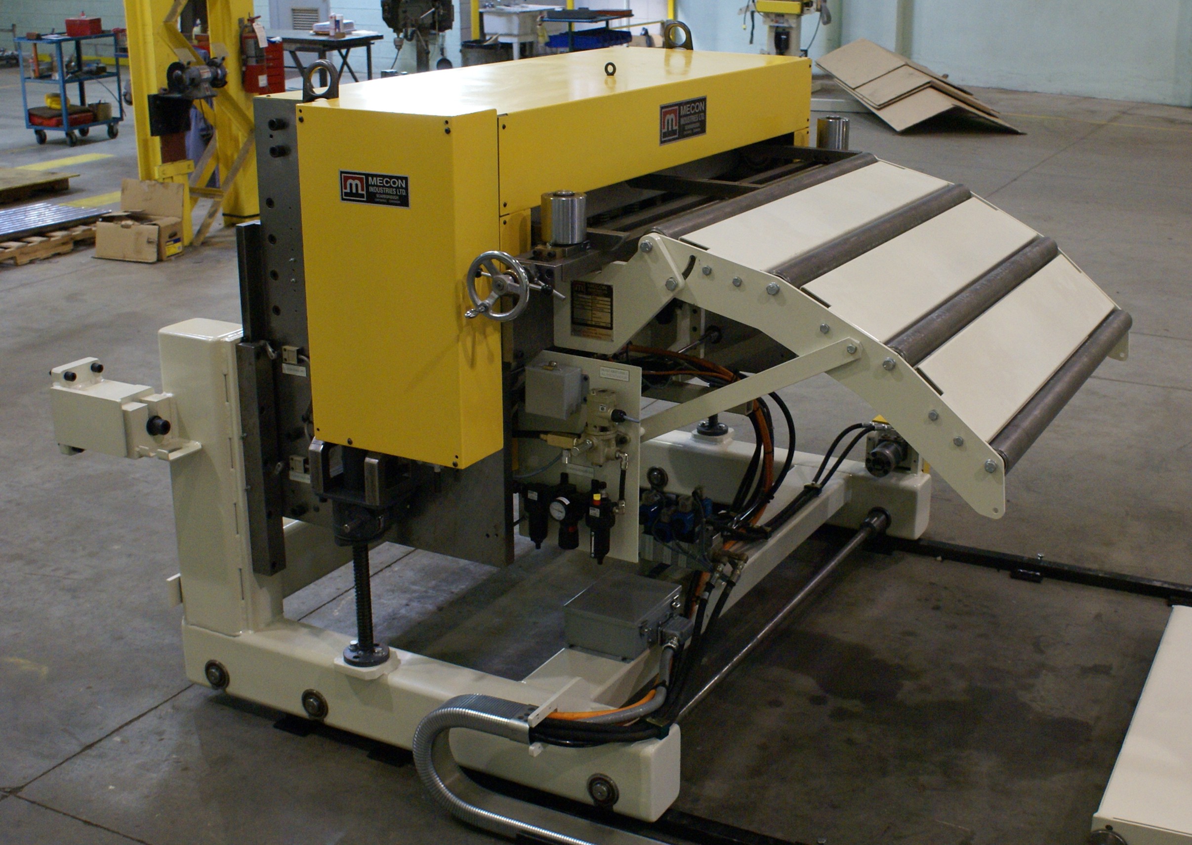
Feeder/Straightener model 6STR36-F
- The machine works with the press to position material in the tooling each press stroke. Cam switches mounted on the press provide the signals to control feeder timing of material move and release of rolls for piloting. The precision drive components between the servo motor and the drive rolls eliminate backlash to ensure accurate, repeating feeds.
- Servo-Drive: brushless AC motor and drive, with integral servo quality gearbox.
-programmable; feed constant, maximum system speed, acceleration rate, manual jog speed, drive direction, etc., program protected by password.
-fast setup of feed length and feed speed through keypad
-diagnostic display of operating status
-detection and diagnostic display of malfunctions, including; invalid parameters, emergency stop, external interrupts, feedback errors, press feed angle signal lost, etc. - HIGH PERFORMANCE
-performance may be tuned for specific requirements.
-feed length +/-.003″ accuracy.(accuracy depends on material and loop conditions, without material machine repeats within +/-.001″)
-the servo gearmotor drives the lower feed roll thru a Gates Poly Chain high performance tooth belt.
-upper roll is driven thru a constant mesh gear train, gears are hardened 4140 steel.
-Upper roll is lifted/lowered by air cylinders.
-air system provides a constant pressure to the roll open side of the cylinders and turns the roll close side of the cylinders on and off.
-feed rolls are steel, induction hardened to 56-58 Rc, precision ground to 6.000″ diameter, surface treated and chrome coated for a hard, high friction surface giving excellent grip and long life.
-feed rolls are supported by precision permanently sealed and lubricated ball bearings.
- SERVO PILOT RELEASE OF STRAIGHTENER ROLLS
-Servo pilot release system uses a servomotor to rotate 2 eccentric shafts to provide 4 point location of the straightener rolls. More energy efficient, reliable with much lower maintenance requirements as compared to hydraulic or air actuated systems.
-Roll lift of 0.5” to allow deeper straightener settings and so allow more work to be done to the materials. Rolls are 1045 steel, 6.000″ diameter, induction hardened to 56-58 Rc, and diameters are precision ground.
-Bearings are Heavy Duty needle rollers running on hardened inner races with seals.
-Straightener rolls are supported by hardened back up rolls to limit deflection when processing heavy materials.
upper 4 rolls of the straightener are not driven and are individually adjustable. The vertical position is set by hydraulic motor, and position is indicated by digital counters with .001″ graduations.
-2 entry pinch rolls, lower roll driven, grip the strip to drive material thru straightener without resetting. Upper roll is lifted/lowered by 2 air cylinders.
-Entry ramp rolls support material to ensure smooth flow thru loop into feeder.
-Hardened vertical side guide rolls align the strip to the tooling. - Floor mount
– the feed head assembly is mounted on an angle plate. The angle plate is supported by a floor mounted base, with 2 gib style slides and a motorized worm jack. The front of the floor base has a machined pad with holes, to attach the base to the press.
**Motorized pass line adjustment of 12″ with a minimum height of 38″ or higher for standard base. - Control Console-Control pedestal contains the operator controls for all functions.
-Power on/off
-Hydraulics on/off
-Drives on/off
-Uncoiler – Pinch automatic / manual
-Coil Car in/out
-Coil Car up/down
-Uncoiler Mandrel expand/retract
-Uncoiler Jog forward/reverse
-Pull Roll open/close
-Pull Roll Jog forward/reverse
-Feeder automatic/manual/feed setup
-Rolls open/close/pilot
-Feeder Jog forward/reverse (Pendant Control)
-Error Clear
-Parameter run/program
-Cycle start/stop
-keypad for entry of parameters, feed length, feed speed etc.
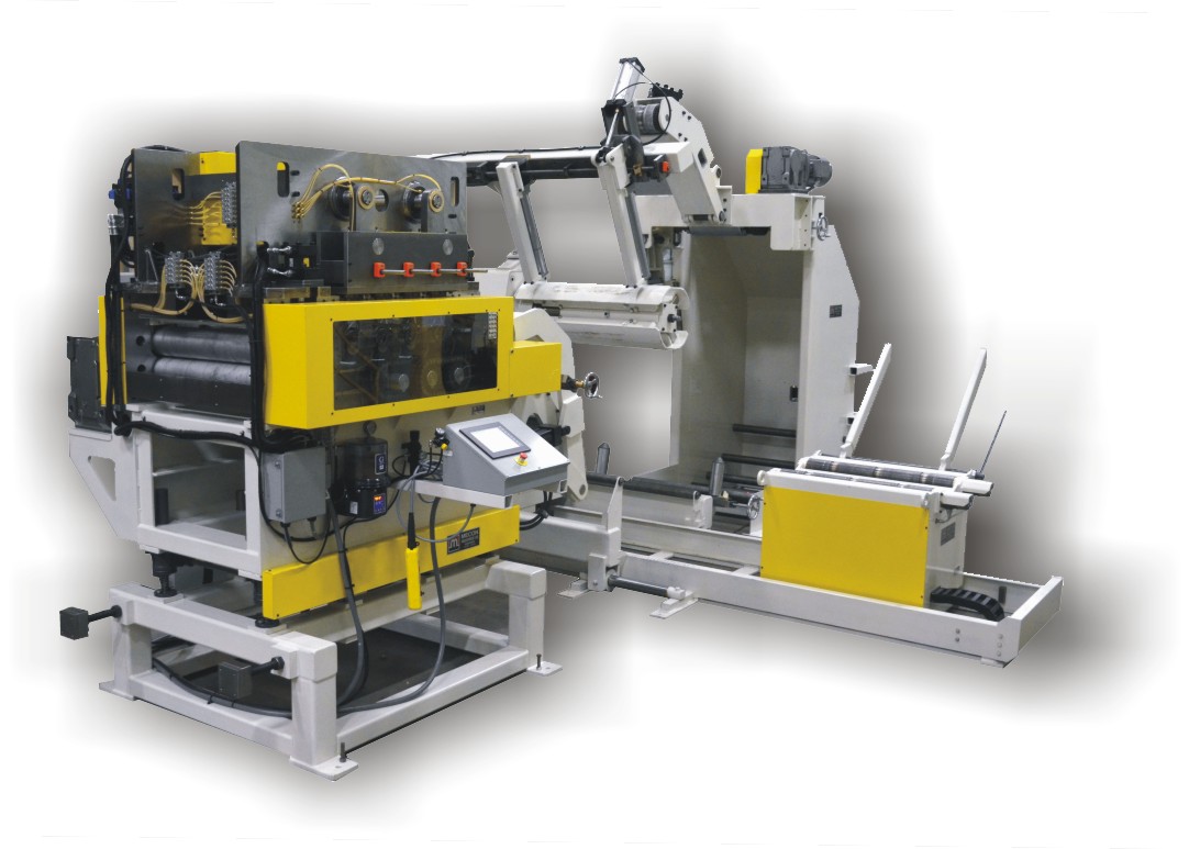
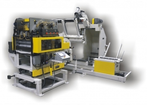
MECON 200CC-pr COIL CAR , 200btj36 UNCOILER, 8pr36-10hp POWER PULL OFF ROLLS, PULL ROLL FRAME AND MATERIAL GUIDEsS, 6STR36-F FEEDER/STRAIGHTENER PILOT RELEASE
System #15409
[embedyt] https://www.youtube.com/watch?v=_OLp0H7ofQ0[/embedyt]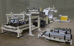
Requirement:
Cut to Length System, Single uncoiler with Coil cart
- 10,000 lb x 48” wide capability
- Material thicknesses:.015”-.060”
- Material: galvanized, galvalume, cold-rolled steel, stainless steel (304, 316, 409, 430, AL29-4C, other) Note: Majority is SS material
- Min/Max coil width: 24”/48”
- Existing available floor space to work within: 35ft long x 10ft wide.
- Min/Max cut length: 9”/51”
- Production rate: 1500 blanks per hour (22” avg cut length)
- Loop control sensor
- Threading table
- Powered straightener
- Servo roll feeder (feed roll accuracy of +/-0.002”)
- Precision Shear
- Shear blade material with high wear resistance (i.e. Cru-wear)
- Minimal shear blade change time (
- 5’ x 5’ Blank stacking system (that will not damage sheared edge) Blanks muststack directly onto existing metal pallets used for laser welder. (See below).
- Quick/easy coil changeover
Important Considerations:
Tight tolerance on length.
Out of square causes problems
Flatness
Rewinding of partial coils
Coil Handling streamline and automate
Stacking system, even stacking very important
Minimize marking.
Proposed Solution:
Coil car – 200cc with Coil keeper arms
- 20,000lbs capacity, 19″ vertical lift, 120″ travel
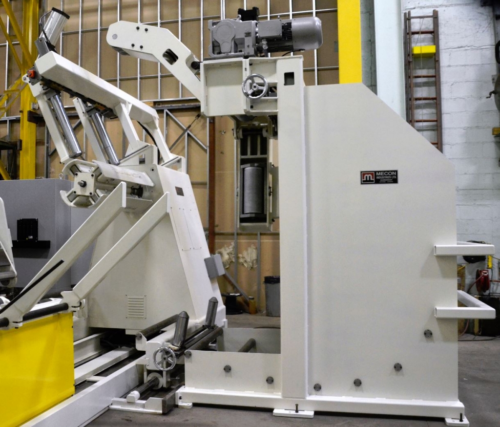
Uncoiler – 200m60
- 20,000lbs. capacity
- 60”, 4 segment mandrel with hydraulic expansion 18” to 22” diameter
- Overarm with idle wheel
- 100” travel base with tractor drive
- Overarm with idle wheel
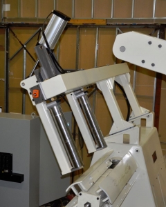
- End Pivot, hydraulic lift threading table EPH 60 x 150
- The threading table is used to eliminate the need for the operator to carry the start of the material from the coil to the straightener .
- Extended entry conveyor with ramp .
- 2 sets side guide rolls with centering screw adjust .
- Coil centerline laser .
Combination Feeder Straightener – 4str60 .
- 11 hardened and ground rolls running on precision needle bearings,
- Bearings lubricated from centralized manifolds (hand lubricated)
- Entrance and exit pinch rolls; air actuated, lower rolls driven,
- 2 entrance pinch rolls, 4.000″ diameter, close onto material to drive starting edge thru straightener, not required to change straightener settings for threading,
- 2 exit pinch rolls, 4.000″ diameter, open for threading, close for running, servo drive with 575v to 440v transformer
- Flex system control HMI with I/O for shear control
- Exit side guide rolls with centering screw adjust .
Shear – 08hs60
- MAXIMUM WIDTH 60″
- THICKNESS .080″ AT 60″ WIDE 60,000 UTS MILD STEEL
- THICKNESS 0.004″
- CYCLE TIME 2 seconds

MECON Cut To Length Line with Conveyor Stacker system
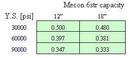
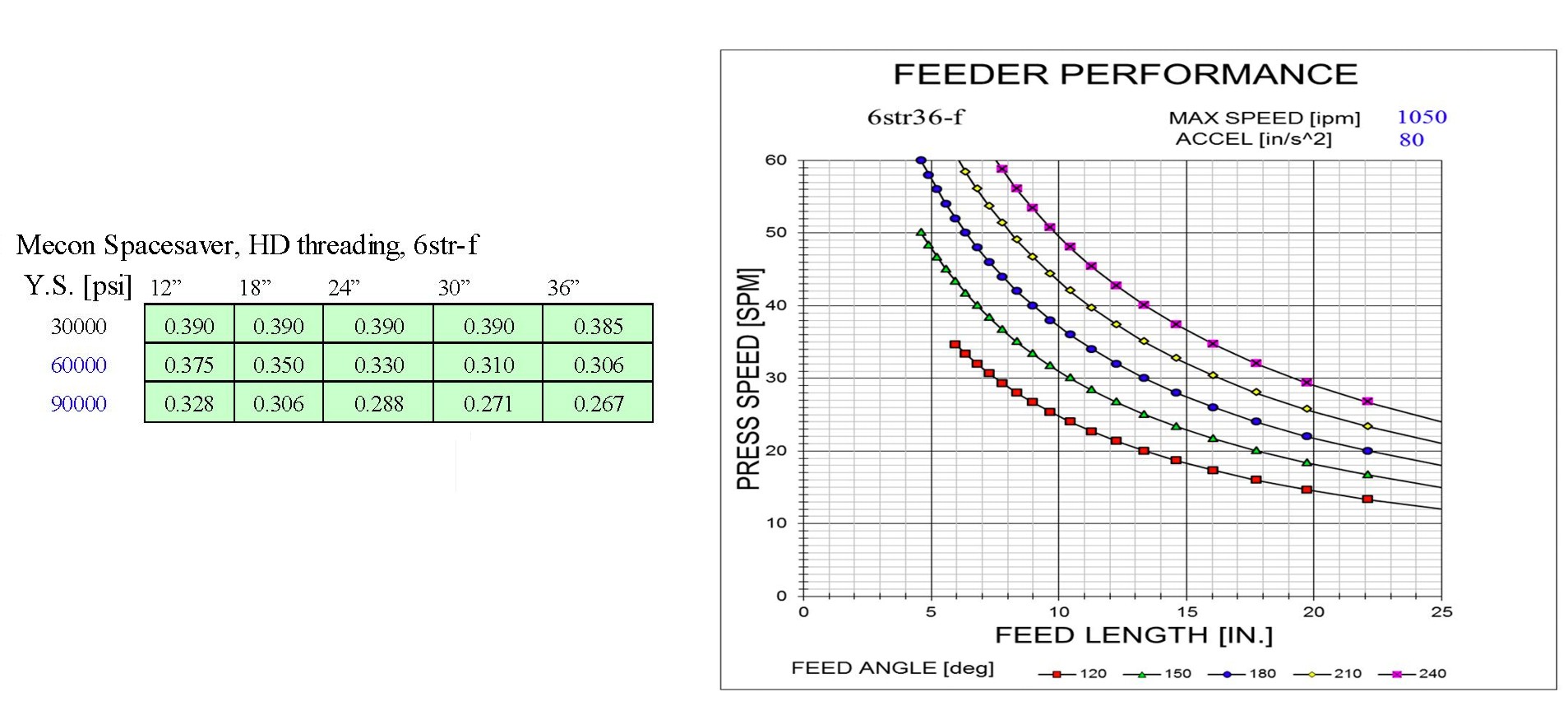
System #11233
Requirement:
1 coil feed system for 3/4”material.
- 20,000 lb x 18” wide capability
- Material thicknesses: up to 3/4″, see below
- Material width: 18″ max.
- Press speed: 20 SPM
- Feed length: Various
- Feed angle: to be determined
- Coil OD.: 72″ max.
- Coil ID.: 18-22″
- Passline: 54″ to 57″
- Quick/easy coil changeover
ys < 30,000 psi
- 1008/1010
- 0.642″ x 8.06″
ys 30,000 to 60,000 psi
- 4130/4140
- 0.414″ x 8″
ys 60,000 to 90,000 psi
- 5120
- 0.508″ x 4.4″
Proposed Solution:
The system offered is comprised of a combination coilcradle-feeder-straightener. The coil cradle and feeder-straightener are both driven by servodrives. The system is designed to run with no loop, the cradle drive and straightener drive are matched electronically.
The servo-drive responds to the press cam switches, and feeds an exact amount each press stroke.
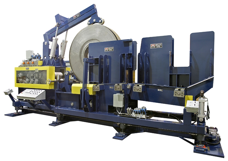
Model 200CSF18 Coil-cradle-straightener-feeder
-CAPACITY 20,000 LB.
-MAX. OD 72″
-MIN. ID 18″
-MAX. THICKNESS see chart
-PASSLINE HEIGHT 52″ TO 58″ POWER ADJUSTMENT
Based on review of the most difficult materials on the specification list we recommend the 8str18 straightener.
Machine frame and drive sizing will match the straightener capacity listed for the 8str18 series straightener.
COMPONENTS.
- Coil Staging Ramp: The coil is set onto a fabricated Vee table with a pivot. Hydraulic cylinders lift the table upward to create a 5 degree down slope to the cradle rolls, or down for staging. A coil catcher / peeler catches and cushions the coil as it rolls into place on the cradle rolls. Coil catcher may be used to push the coil off the cradle rolls to the staging station.
- Side Guidance: Side walls on both sides of the coil are set to coil width to contain the coil and reduce telescoping. Side guide rolls are set in the walls beside the cradle rolls to reduce friction between the coil and the wall during feeding. Wall position is set by limit screws and open / closed by hydraulic cylinders. Walls open to rated coil width plus 10” to allow cutting and removing of coil retaining bands.
- Vertical side guide rolls are set at the entry of the straightener
- Coil overarm: Telescoping overarm with dual rollers is set to hold the coil down onto the cradle and help contain the coil when the bands are cut. Actuated by hydraulic cylinders.
- Cradle: The coil is supported on 2 hardened cradle rolls X 7.750 inch dia..
- Cradle rolls are driven by a servo-gearmotor
- Cradle side plates are self centering and are power adjusted.
- Threading system: Peeler / prebender pivots and extends to the side of the coil to guide and wrap the start of coil over the ramp rolls mounted between the cradle and the straightener. The entry pinch roll opens to catch the start of coil, closes to grip and drive the material through the straightener.
- Feeder-straightener: model 8str18 Rolls are 1045 steel, 10.000″ diameter, induction hardenned to 56-58 Rc, and diameters are precision ground. Bearings are Heavy Duty rollers running on hardenned inner races with seals.
- 6 roll straightener: 3 upper rolls over 3 lower rolls.
- Lower rolls are driven and fixed position
- Upper rolls are not driven and are individually adjustable.
- Straightener rolls are adjusted by hydraulic motors, roll position is indicated by digital counters with .001″ resolution.
- Rolls are 1045 steel, 10.000″ diameter, induction hardened to 56-58 Rc, precision ground, shot peened and chrome coated for excellent wear resistance and grip
- 2 entry pinch rolls, upper and lower roll driven, grip the strip to drive material thru straightener without resetting. Rolls open up 3″ for easy threading.
- 2 exit feed rolls, upper and lower roll driven, grip the strip to drive material thru straightener without resetting.
- Lift system: The machine height is set by motorized worm screw jacks with 6″ adjustment. Jack feet are set onto floor pads. 2 guide posts mounted to the front mount plate prevent side movement.
- Controls: Control console contains the operator buttons and drive system including;
- Pendant jog control to allow operator to position strip from a remote location.
- Power on, Cradle sides in/out, Emergency Stop, Drives on/off, Roll controls, Cycle start/stop, Mode selection, Length and speed inputs, main power disconnect.
- Feed to length control requires a Press Operated Control Relay (Feed Cam) to close at start of feed, and remain closed until feeding is not permitted.
- Servo system – Bosch Indradrive, Yaskawa or equivalent, HMI to allow programming of system parameters, feed length, speed, and display of operating mode, fault status and code.
- Optional – side shift system: The machine will be mounted on sideways slides and shifted by hydraulic cylinders. Front and rear are set independently with position indicated on scales.
Model 200CSF18 Coil-cradle-straightener-feeder
Requirement: 50,000 lbs. x 72” wide Steel coiled material to be stored, uncoiled, straightened, and fed into a press.
Maximum coil weight: 50,000 lbs.
Min/Max coil I.D.: 19 ½” -24 ½”
Max coil O.D.: 72”
Press: PTC
Passline ht: to be determined
Feed angle: 180 degrees
Material: .020″ to .236″ (6mm) mild steel and hsla,
Material: .08 x 60″ 50ksi ys steel
Material: .120” x 72” (3 mm) x 50 ksi,
Material: .177” x 56” x 50 ksi ys HSLA
Performance: 15” x 48 spm, 24” x 30 spm
Power supply: 480 volt, 3PH, 60Hz
Air supply: 80 psi
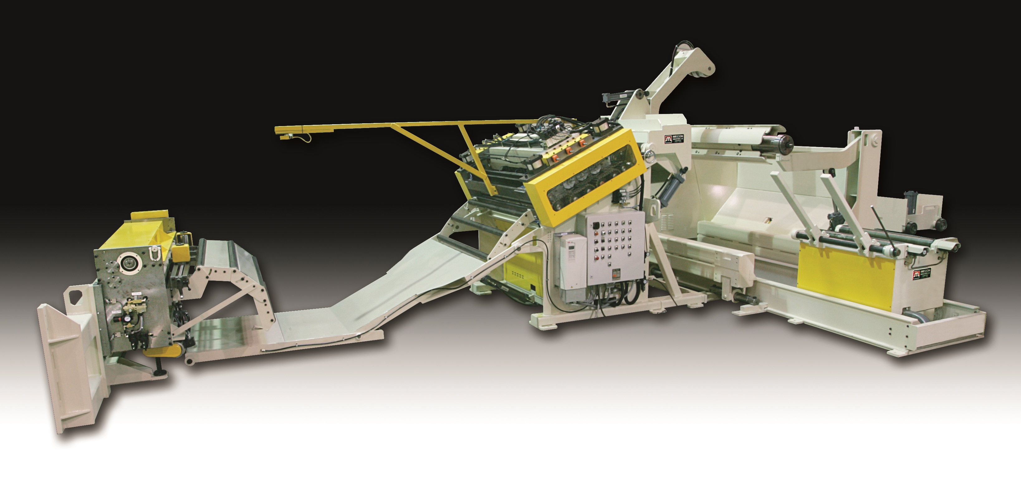
Proposed Solution: Coil car, Uncoiler, Power Straightener, accumulation loop, Feeder.
a) Coil car model 500cc with power top rolls:
- A coil car with power lift of 20″ and power travel.
- The car will travel on tracks to transfer the coil from the park position to the uncoiler, or from the uncoiler back for storage. The coil rests on non-powered rollers.
- The rolls are used to aid in threading thicker materials into the straightener. Traverse, and lift functions are controlled manually from a central control station.
b) Uncoiler model 500btj72. ( capacity 50,000 lbs x 72” with spindle end support)
- The uncoiler has an air brake to maintain coil tension during processing.
- A hydraulic motor, and clutch for jogging coil. Jog speed 4 rpm.
- Upgrade to heavy duty back tension brake with coil diameter sensor to maintain constant tension during unwind of coil.
- The mandrel is 4 segments, with wedge style expansion and is hydraulically expanded/retracted.
- Inside diameter range of 19.5 to 24″.
c) Coil over arm with power wheel: Peeler / coil breaker.
- The over arm clamps onto the coil to contain the coil end when the straps are cut.
- The wheel is powered by a hydraulic motor and drives the coil to thread the start of the coil to the input pinch rolls of the straightener.
- The Peeler extends to contact the coil and guide the start of the coil.
- The coil breaker lifts to press the strip against a flattenning block on over arm and thus de-kink the start of the strip. This allows easy threading of steel into straightener.
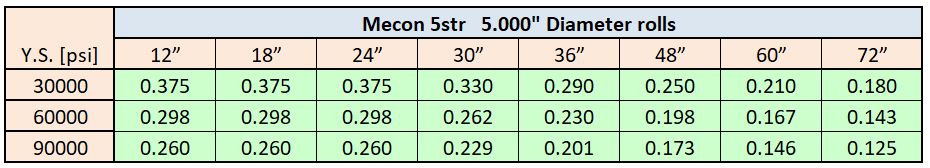
d) Straightener model 5str72-bu: Series straighteners have:
- 11 hardened and ground rolls running on precision needle bearings, bearings lubricated from centralized manifolds (hand lubricated)
- Entrance and exit pinch rolls; air actuated, lower rolls driven.
- 2 entrance pinch rolls, 5.000″ diameter, close onto material to drive starting edge thru straightener, not required to change straightener settings for threading.
- 2 exit pinch rolls, 5.000″ diameter, open for threading, close for running.
- 7 straightenning rolls, 5.000″ diameter, 4 lower rolls all driven, 3 upper rolls idle.
- Upper rolls motorized individual adjustment, position shown on .001″ graduation counters.
- Straightener drive: Variable Frequency AC Motor control with AC induction motor, and brake.
speed 0-80 fpm. infinitely variable. These drive systems give very smooth acceleration and deceleration with no sudden shocks to the material or drive components, and thus extend machine life and limit material marking. - In automatic mode a sonar unit senses the height of the material in the loop between the straightener and the feeder.
- The sensor signals the drive to speed up or slow down to maintain the loop automatically.
- The uncoiler brake is provides back tension to limit coil overrun and to help prevent coil slack.
- n manual mode the speed is set at a low speed and forward or reverse movements are selected by pendant mounted switches.
- HD Support rolls: The drive system will be increased to 40 hp to match the higher capacity of the straightener. Each straightener roll is supported by rolls to limit roll deflection when processing heavy materials. Lower support roll positions are fixed and not adjustable. Upper support rolls travel with the straightener roll during adjustment.
- Material guidance: Coil peeler and breaker guide material into straightener.
- Entrance vertical guide rolls to track the material.
- Exit ramp rolls support strip as it exits straightener and drops into loop.
System Summary:
a) COIL CAR: MODEL #500CC .
- 20″ lift .
- Keeper arms .
- power rolls .
b) UNCOILER: MODEL 500BTJ .
- 72″ mandrel .
- side shift uncoiler .
- xHd btj base .
- coil diameter brake control .
c) THREADING: MODEL HD72 .
- motorized overarm wide roll std
- coil breaker table std
- peeler arm std
d) STRAIGHTENER: MODEL 5STR72 .
- 40 HP VFAC drive .
- power adjust strnr .
- Stnr support rolls .
- main transformer .
- Sonar loop control .
e) END PIVOT THREADING TABLE:
f) SYSTEM INTEGRATION:
g) FEEDER: MODEL 600F72-IHD
- floor base power elevation .
- 3 ph. isol. transformer
h) Estop and Gate monitor circuits .
- Hydraulic cylinders actuate the table. The table lifts to support material between the straightener and the feeder as the beginning of the strip is being jogged to the feeder.
- Table length is dependent on the loop geometry, which is related to the maximum material thickness, material strength and feed length.
f) Straightener control station and integration:
- Contains the controls for the coilcar, uncoiler, overarm/peeler/breaker station, the straightener, and the threading table.
g) Feeder model 600f72-IHD: The feeder is a floor mounted machine with a press adapter bracket, a seperate control console and a remote jog pendant. The press adapter bracket rigidly attaches the feeder to the press. The jog pendant allows the operator to walk with the material when threading.
- Feed Rolls: The rolls are 73.5″ face width x 6.000″ diameter. They are hardenned, precision ground and 100rms chrome surfaced for excellent grip and wear resistance.
- Upper and lower rolls are both driven.
- Passline Adjustment; Passline height is adjusted by a powered elevator, total adjustment 12″.
- Pilot release: The feed rolls are pnuematically lifted and lowered. The pilot release circuit is signalled by a press cam to lift the rolls and lower the rolls to release the material.
- Anti-Backup brake mounted on the motor is standard. The brake is spring engaged and is on anytime the power is off the servo motor. When the pinch rolls are contacting the strip, the brake will not allow the material to slip back into the loop.
- Servo-Drive: An Indramat high performance brushless AC servosystem drives the feed rolls. It is conservatively rated and is capable of peak torques well in excess of the rated torque.
- The servo motor is mounted to a servo quality “zero” backlash gearbox, and mounted under the feed rolls. A high performance Gates Polychian drive connects the gearbox output shaft to the lower feed roll. Components Mkd Motor, Alpha Sp gearbox.
- Computer Control: An Indramat motion control – Mecon OCS control runs the servodrive. It is very flexible. Program parameters, speed and feed length, etc. are input directly through keypad. Displays operating mode, error and system diagnostics, etc.
- Very fast setup of next job.
- Die and press protection through monitoring of press feed signal and feed completion.
- High Performance: The performance is tuned to suit the specific requirements. Feed length accuracy better than +/- .003″
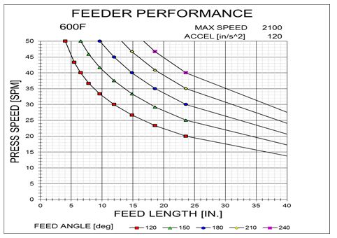
Typical 600f72 set up
a=240 in/s/s,, feed angle = 180 degrees, maximum uncoiler speed = 80 fpm
20 spm —- 45″ progression
30 spm —- 28″ progression
40 spm —- 20″ progression
h) Safety circuits. The control is wired with dual path Emergency Stop and Gate Monitor circuits. The control relays are Safety rated contactors with external reset.
- On Emergency stop, all high voltage power is disconnected from drives and hydraulic power unit, and 120vac and 24vdc power is disconnected from all solenoid valves, control power remains connected.
- On Gate monitor circuit open, the system will allow manual functions, but will prevent automatic functions.
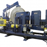
MECON 50,000 lb. Capacity x 72” Width Coil Handling System
System #15690
Requirement: Uncoil 2 steel coils at the same time
Material: Steel 30,000 psi
Thickness: 20Ga
Width: 2″-15″
Coil weights: 1500 lbs
Process speed: 200 fpm
Press speed: 120spm
Proposed Solution:
Dual UNCOILER model T15M16
- CAPACITY 1,500 lbs. per spindle
- MAXIMUM WIDTH 16″
- COIL ID. RANGE 12″ to 21″
- COIL MAXIMUM OD 60” typical
- dual spindle uncoiler,
- 3/4 hp DC spindle drive on each spindle
- Drives are controlled manually for jogging the coil, and automatically by the loop controlers during run.
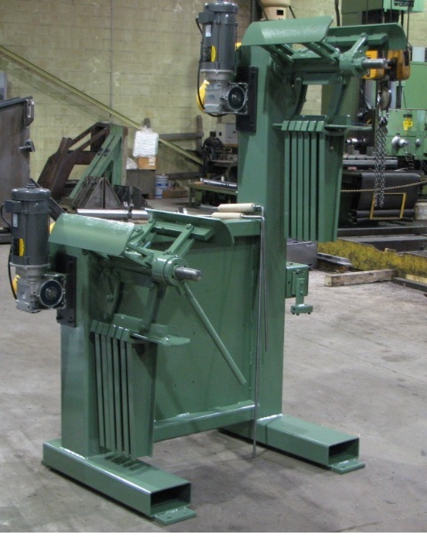
MECON model T15M16 Tandem spindle uncoiler with 2 complete 15M uncoiler spindles
Requirement:
Material: Steel 70,000 psi
Thickness: 3/8”
Width: 8”
Coil weight: 10,000 lbs
Process speed: 34 fpm
Feed length: 8”
Press speed: 50spm
Pass line height: 46″
System voltage: 575v, 3-phase, 60 Hz;
Proposed Solution:
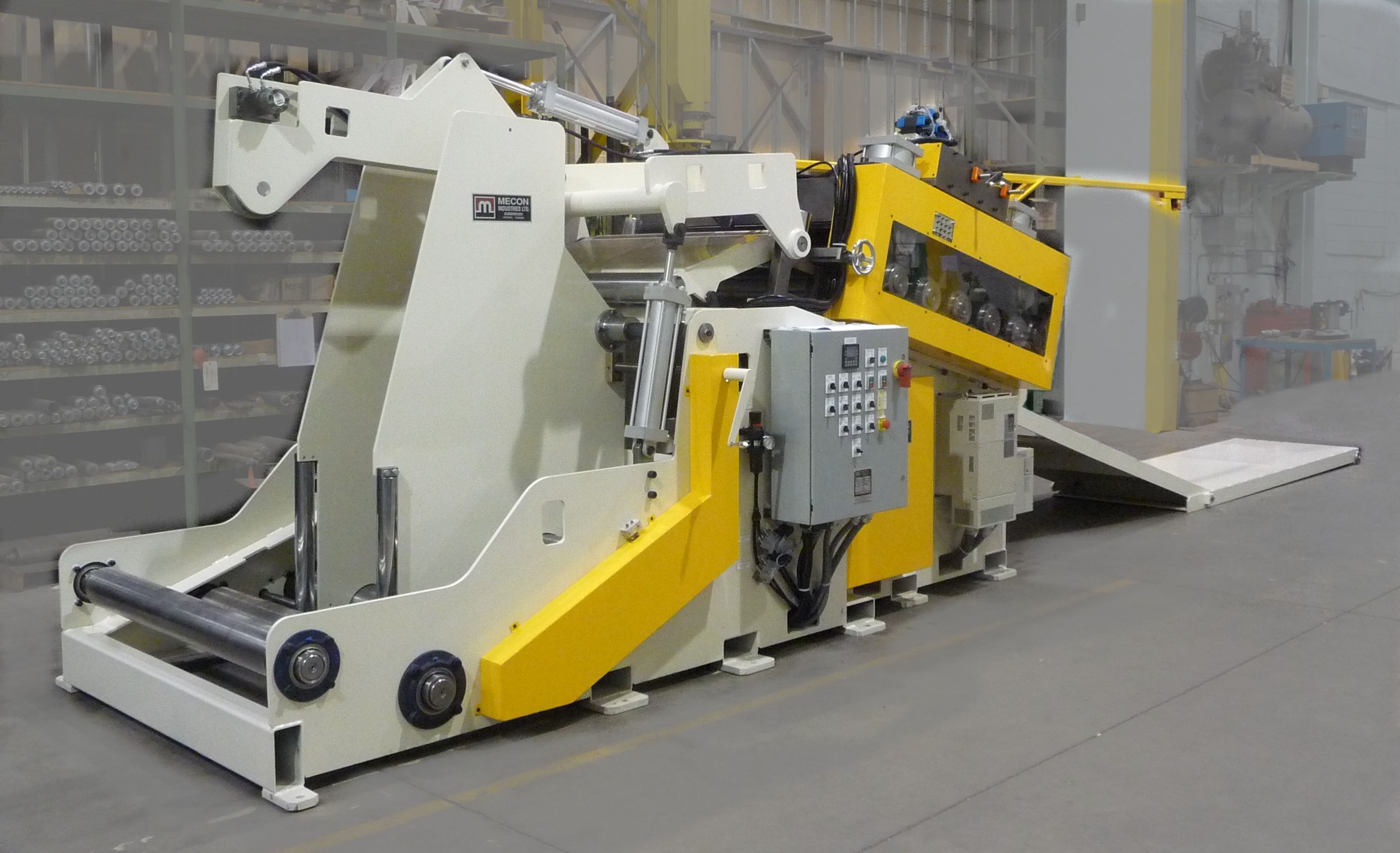
COILCRADLE – STRAIGHTENER: 200CCS18
- 6str18 straightener upgrade
- motorized straightener adjustment screw
- adjust side guide rolls side plate rolls
- drive upgrade to 20 hp
- laser loop control
- extra heavy duty threading
- end pivot threading table
FEEDER: 600F18 with Antibackup brake
- Floor base- power pass line adjust
- Screw adjust sideguide with offset adjust
MECON SERVO FEEDER 600f
with screw adjust side guides and rolling floor base.
Capacity: 3/8” x 18″ wide
Maximum Width: 37.5″ for model
COILCRADLE – STRAIGHTENER: 200CCS1 8-6STR
Capacity: 3/8” x 18″ wide
Maximum Width: 19.5″ for model
Maximum coil wt: 20,000 lb